
CONTIGUOUS BORED PILE WALL
-
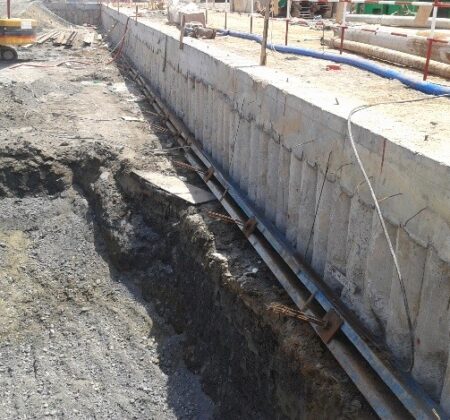
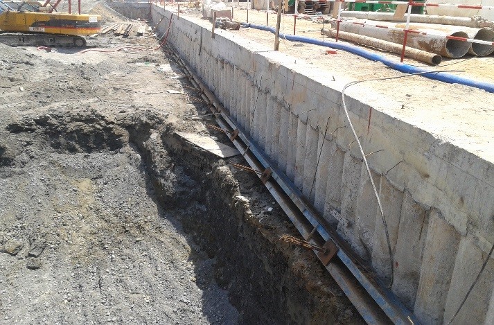
Retaining walls are structures that hold back soil or rock from falling due to landslides caused by gravity or erosion. Watertight retaining walls (cofferdams) are employed in conjunction with an appropriate dewatering scheme to hold back water and clay in wet areas. In deep excavations, these walls have to withstand great lateral earth pressures and hydrostatic pressures caused by ground water. Depending on design requirements, several pile types and configurations are used to construct retention systems.
-
Closely spaced piles used to form retaining walls in areas where water inflows are not significant. Their main use is in clay soils and they may also be used to retain dry granular materials or fills. In water bearing granular soils, seepage is likely to occur in the gaps between the piles which can be prevented by grouting these gaps to form a watertight retaining wall.
SECANT BORED PILE WALL
-
Secant (tangent) piles are interlocking piles that form a continuous watertight wall. A continuous reinforced concrete guide wall is constructed to pinpoint the location of each overlapping pile. Piles are spaced a distance which is a little less than one pile diameter. The exact spacing depends on construction tolerances.
-
Alternate piles (known as "female", "intermediate" or "primary" piles) are drilled inside temporary steel casing and constructed without reinforcement using a slow setting concrete. Temporary casing is extracted while the concrete has not fully set and heavy casing is then driven into the intervening pile location cutting into the fresh concrete of the adjacent female piles, the "male", "secondary" or "king" piles are then promptly drilled.
-
The male pile steel cage reinforcement is inserted and structural concrete is poured adhering to the female pile concrete on either side to form a watertight continuous wall.
SHEET PILE WALL
-
Sheet Pile walls are constructed by driving prefabricated reusable panels into the ground. These panels are driven into ground using a vibratory hammer in such a way that each panel interlocks with the adjacent one on each side. Soil conditions may allow the interlocking sections to be vibrated into ground instead of being hammer driven. The series of panels vertically interlock to form a continuous impermeable wall.
-
The full wall is formed by connecting the joints of adjacent sheet pile sections in sequential installation. Sheet pile walls provide structural resistance by utilizing the full section. The reusable panels are made from a variety of materials such as steel, wood, plastic and fiberglass. Steel sheet piles are however, the most commonly used in deep excavations.
-
Sheet piling provides an efficient, economical and timesaving solution in certain types of applications such as cofferdams, cut and cover tunnels, retaining walls, seawalls, and containment walls. They are however, constrained by the depth of excavation, the magnitude of the lateral pressures, and the stratum they can penetrate.
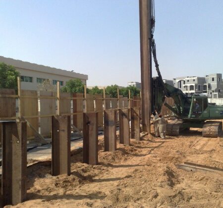
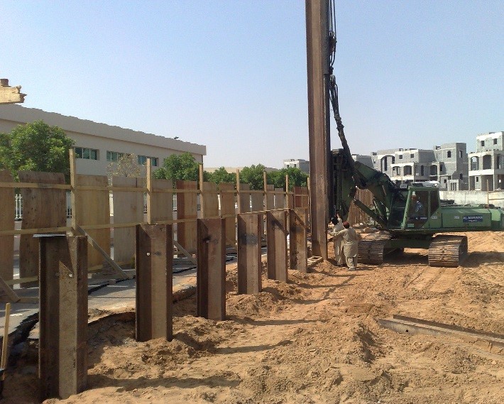
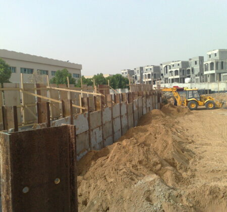
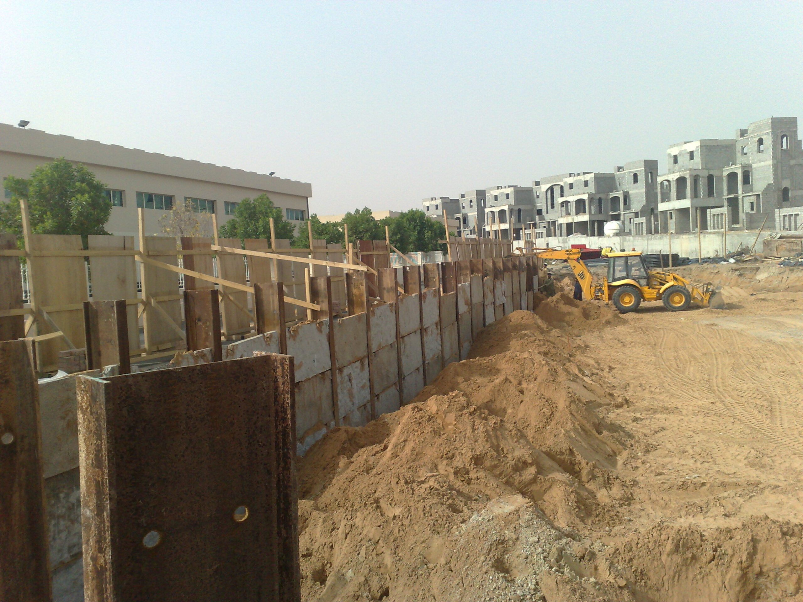
SOLDIER/KING PILE AND LAGGING WALL
-
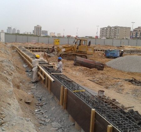
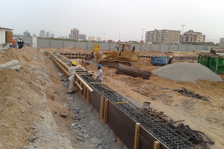
Soldier piles, are steel wide flange H-beam piles spaced 1 to 3 meters apart. They are driven into the ground prior to excavation by a vibratory or impact hammer or may be installed in drilled shafts and backfilled with concrete. Their main purpose is to provide permanent or temporary shoring for vertical excavation.
-
After insertion into the ground, the area between each two piles is excavated and timber, steel or precast reinforced concrete panel lagging is inserted between the H-pile flanges as the soil is excavated in stages downward. The void space behind the lagging is then backfilled and compacted. Lateral earth pressures are transferred from the lagging onto the soldier piles. In high water table conditions, an extensive dewatering scheme is required with this type of retention system.
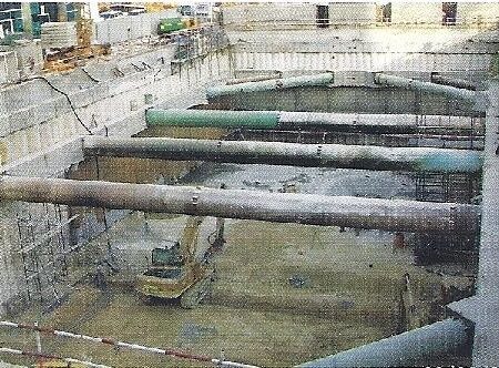
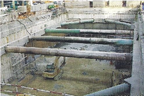
STRUTTING AND BRACING SUPPORT
-
In situations where anchors cannot be used or only temporary retaining wall support is required or for other reasons struts are used to provide such support during excavation. Strut dimensions and layout is pre-determined by design engineers. After underground installation of the retaining wall system, ground is excavated and struts are installed at each specified level once it has been reached. The base slab is then constructed , the lowest level strut is removed and side walls are constructed. The same procedure is followed progressing upwards towards other slut levels until the roof slab is constructed. The area between the retaining and side wall is backfilled and then the first level strut is removed.