Depending on the structure they are carrying, piles can be subject to axial (tension/compression), lateral loads or a combination of any or all loads. Some of the sources for such loads are:
• The weight of the supported structure.
• Earth and water pressures on retaining wall systems.
• Wind loads.
• Eccentric vertical loads.
• Loads from waves and currents for offshore structures.
• Slope movements.
Piles are arranged in a number of ways so that they can support load imposed on them. Vertical piles can be designed to carry vertical (compressive and uplift or tension) loads as well as lateral loads. Vertical piles are sometimes combined with raked piles to support lateral and vertical forces. Pile caps distribute axial loads evenly over individual piles in a group. However, when a group of piles is subjected to a lateral load or a combination of vertical and lateral loads the resulting moment forces are taken into account during calculation of load distribution.
Several factors are taken into consideration when designers select pile types, grouping and distribution:
• The loads that the foundation system will carry (magnitude and direction).
• Load-bearing capacity of the foundation soil and all other pertinent geotechnical data.
• Safety factors to be incorporated into the design.
• The type of structure being built.
• Special design needs, such as resistance to vessel impact or seismic forces.
• All relevant codes, standards and project specifications.
• All applicable statutory and regulatory requirements.
Pile foundations develop their load carrying capacity by transferring the loads to the bearing ground. End-bearing piles transfer these loads to the hard strata or rock where it rests, while friction and cohesion piles transfer loads to the adjacent ground grabbing the surface of the pile through skin friction. Designers rely on any or a combination of both of these supports in their design.
RETAINING WALL DESIGN
The variables, unknowns and constraints involved in retaining wall design are many, making it a complex and challenging task. A retaining wall design has to account for a number of factors, foremost being the stability of the wall itself. A thorough analysis of the geotechnical investigation report, project requirements, construction sequence, type of proposed structure and other factors is initially performed by design engineers.
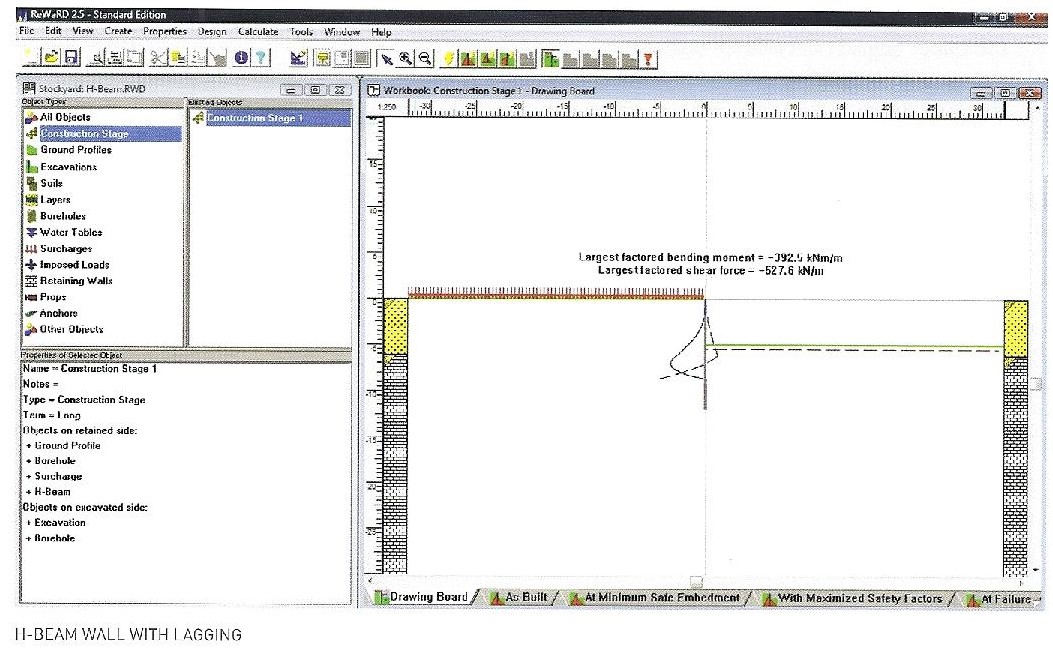
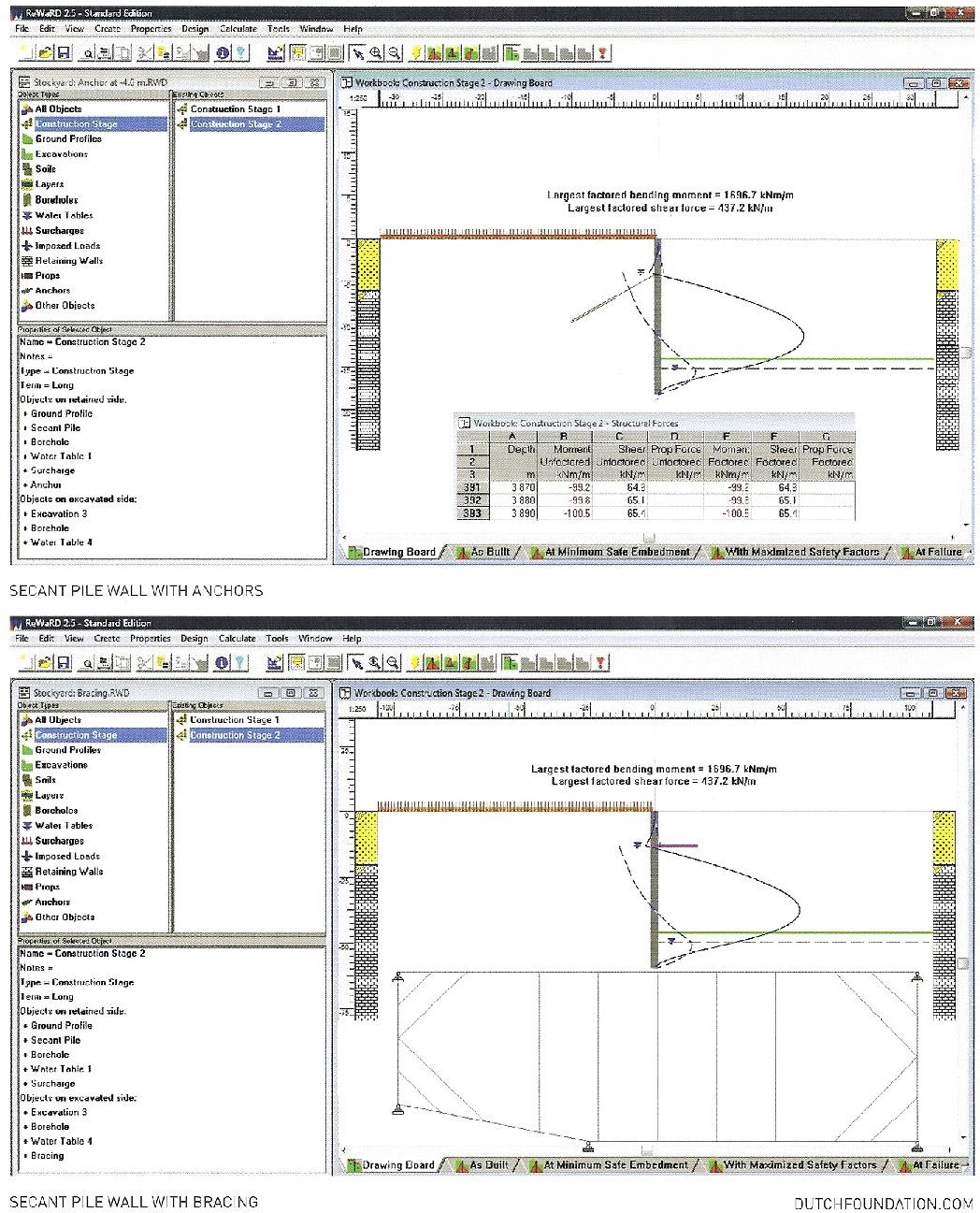
This analysis, coupled with the experience of the designers, generates the first input for computer software such as ReWaRD® from Geocentric and STAAD.pro® from Bentley] to further analyze the c01plex loads and perform the calculations. Typically, a retaining wall designer has to consider the following:
PRESSURE
Earth and water pressures that are expected to act on the wall.
EXTERNAL STABILITY
The overall external stability of the retaining wall acting as one whole body [sliding and overturning]. Sliding instability is caused by horizontal forces while overturning is caused by the moments generated from these factors.
BEARING STABILITY
Overturning increases stress at the wall toe and decreases them at the heel; the bearing capacity of the foundation soil has to be considered to ensure that wall settlements are kept within acceptable levels.
GLOBAL STABILITY
Even when external and bearing stabilities are acceptable, retaining walls may still be susceptible to an overall rotational type failure. This type of failure originates well below the retaining wall itself due to weaker soil zones.
STRUCTURAL INTEGRITY
After a satisfactory stability design, structural calculations are made on the wall itself to determine the proper sizing of longitudinal and shear reinforcement.
RETAINING WALL SUPPORT
Designers have to also consider if the retaining wall itself requires further support [such as anchoring or bracing].
SAFETY FACTORS
An appropriate factor of safety is incorporated into the design calculations for each element of the design criteria.


